LoRaWAN has emerged as a groundbreaking technology for the Internet of Things (IoT), offering long-range, low-power connectivity that empowers diverse applications from smart cities to industrial monitoring and asset tracking. Its promise of wide-area coverage with minimal energy consumption makes it ideal for remote sensors and devices in often challenging environments. However, the true strength of any LoRaWAN network lies not just in the technology itself, but in its meticulous deployment.
Many new LoRaWAN installers, eager to harness its potential, often overlook critical best practices during gateway and antenna deployment. This oversight can lead to suboptimal performance, reduced range, increased packet loss, and ultimately, a disappointing return on investment. The difference between a struggling LoRaWAN network and a thriving one often boils down to understanding and implementing smart installation techniques.
This comprehensive guide is designed to equip new LoRaWAN installers with the essential knowledge and practical advice needed to significantly boost their signal strength and ensure robust network performance. We’ll delve into the crucial environmental and physical factors that dictate signal propagation, offering clear, actionable strategies to optimize your LoRaWAN deployment from the ground up.
Understanding LoRaWAN Signal Propagation
Before diving into installation specifics, it’s vital to grasp the fundamentals of how LoRaWAN signals – like all radio frequency (RF) signals – travel through an environment. Unlike wired connections, wireless signals are subject to a multitude of interferences and attenuations that can severely impact their range and reliability. A basic understanding of these principles is the first step toward smart installation.
LoRaWAN operates in unlicensed sub-gigahertz radio bands (863−870 MHz in Europe, 902−928 MHz in North America, etc.). These frequencies offer a good balance between penetration capabilities (better than 2.4 GHz Wi-Fi) and antenna size (smaller than HF bands). However, they are still susceptible to environmental challenges.
Key concepts include:
- Line of Sight (LOS): The ideal scenario where there’s an unobstructed path between the transmitting and receiving antennas. This maximizes signal strength and reliability.
- Obstruction Loss: When signals encounter objects (buildings, trees, terrain), they can be absorbed, reflected, or diffracted, leading to signal attenuation.
- Multipath Fading: Signals can arrive at the receiver via multiple paths (due to reflections), causing interference and signal degradation. This is particularly prevalent in urban environments.
- Noise: Unwanted electrical or radio energy that interferes with the desired signal, reducing the signal-to-noise ratio (SNR) and making it harder for the receiver to decode transmissions.
By understanding these principles, we can strategically plan our installations to mitigate negative impacts and optimize signal integrity.
Environmental Factors: Reading the Landscape for Optimal Coverage
The physical environment around your gateway and antenna profoundly impacts signal performance. Ignoring these factors is a common pitfall. A successful LoRaWAN deployment begins with a thorough understanding of the terrain and surrounding structures.
Go High to Clear Obstacles: The Fresnel Zone Principle
One of the single most impactful pieces of advice for any LoRaWAN installer is to elevate your antenna. This isn’t merely about getting a better view; it’s fundamentally about clearing the Fresnel Zone.
What is the Fresnel Zone?
Imagine the direct line of sight between your LoRaWAN gateway antenna and a remote sensor. Radio waves don’t travel in a single, thin line; they spread out in an elliptical, cigar-shaped region around this line. This region is called the Fresnel Zone. For effective communication, it’s crucial that a significant portion of this zone (ideally, at least 60% of the first Fresnel Zone) is clear of obstructions.
Obstacles within the Fresnel Zone, even if they don’t block the direct line of sight, can cause signal reflections and diffractions. These delayed or altered signals can arrive out of phase with the direct signal, leading to destructive interference and significant signal loss. This phenomenon is known as Fresnel Zone obstruction loss.
The calculation for the radius of the first Fresnel Zone (R1) at any point along the path is given by:
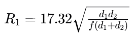
Where:
- R1 is the radius in meters.
- d1 is the distance from the transmitter to the point of interest in kilometers.
- d2 is the distance from the receiver to the point of interest in kilometers.
- f is the frequency in GHz.
For LoRaWAN operating around 0.8 – 0.9 GHz, the Fresnel Zone can be surprisingly large. For example, over a 5 km link, the Fresnel Zone could have a radius of tens of meters at its widest point.
Why Elevation Matters:
- Clearing Physical Obstacles: Elevating the antenna above trees, hills, and buildings directly helps clear the Fresnel Zone, minimizing signal attenuation from absorption and reflection.
- Extended Line of Sight: A higher antenna literally “sees” further, extending the maximum possible range.
- Reduced Ground Reflections: Placement at appropriate heights can minimize destructive interference from signals reflecting off the ground.
Practical Deployment Tips for Elevation:
- Rooftop Mounts: Position the antenna at least 5−7 meters above the building rooftop to ensure it clears obstructions directly on the roof and provides a wide view.
- Mast Extensions: Consider using mast extensions to raise the antenna even higher, especially in densely built-up or heavily forested areas.
- Terrain Analysis: Before deployment, use tools (e.g., Google Earth, specialized RF planning software) to analyze the local topography and identify potential signal obstructions from hills or large buildings. A preliminary site survey can involve measuring background noise and mapping terrain.
- Avoid Antenna Pockets: Ensure the antenna isn’t nestled in a “pocket” formed by taller surrounding structures on a rooftop, which can create localized blind spots.
Beware of “Water Walls”: Signal Absorption by Water
Water is a remarkably effective absorber of radio signals, particularly at LoRaWAN frequencies. This absorption can create significant signal “dead zones” or severely attenuate signals, forming what we metaphorically call “water walls.”
Sources of Water Walls:
- Rain and Fog: Heavy rainfall or dense fog can significantly dampen signal strength over distance. While you can’t control the weather, understanding its impact helps in link budget planning.
- Dense Crowds: Human bodies are composed largely of water. A dense crowd of people between your gateway and a sensor can act as a partial “water wall,” absorbing signals.
- Wet Foliage: Trees and dense vegetation, especially when wet, are major signal absorbers. A thick forest can be impenetrable for LoRaWAN signals.
- Fresh Concrete: Concrete contains a substantial amount of water during its curing process. Freshly poured or recently cured concrete structures can significantly block signals.
Mitigation Strategies:
- Line of Sight for Foliage: When planning deployments in areas with extensive greenery, try to establish line of sight above or around dense foliage.
- Antenna Placement in Urban Areas: In urban environments with high foot traffic, prioritize antenna elevation to clear the immediate ground-level obstructions caused by crowds.
- Consider Building Materials: Be aware of newly constructed buildings or major renovation projects using concrete in your coverage area. Signal penetration will likely be poor until the concrete fully dries.
Identify Indoor Signal Blockers: Modern Building Challenges
Modern architecture, while aesthetically pleasing and energy-efficient, often presents formidable challenges for LoRaWAN signal penetration. Buildings are not uniform in their construction materials, and some are particularly adept at blocking wireless signals.
Common Indoor Signal Blockers:
- Reinforced Concrete: The rebar (steel reinforcing bars) within concrete acts as a Faraday cage, effectively attenuating or blocking radio signals. The thicker the concrete, the worse the penetration.
- Low-Emissivity (Low-E) Glass: This type of glass, popular for its energy-saving properties, often contains a thin metallic coating. This metallic layer can be highly reflective or absorptive to radio waves, turning windows into signal barriers.
- Metal Structures: Large metallic objects like elevator shafts, heating ducts, and structural steel beams can reflect and absorb signals, creating complex multipath environments or complete dead zones.
- Utility Infrastructure: Utility providers often install meters in underground chambers made of soil and concrete, where signals are significantly swallowed. For such spots, expect to calculate a link budget with a 10−12 dB margin and plan for repeaters or specialized antennas.
Strategies for Overcoming Indoor Blockers:
- Indoor Gateway Placement: For extensive indoor coverage, multiple indoor gateways might be necessary, strategically placed to cover different wings or floors.
- Repeater Nodes: In large buildings or complexes, LoRaWAN repeaters can extend coverage into hard-to-reach areas.
- External Antennas: For sensors deep within buildings or basements, consider using external antennas for the sensors themselves, run to a point with better signal access.
- In-Building Surveys: Conduct detailed site surveys within challenging buildings to identify signal dead zones and plan gateway placement accordingly.
Physical Factors: Smart Installation Techniques for Robust Signals
Beyond environmental considerations, the physical aspects of your LoRaWAN gateway and antenna installation are equally critical. The choices you make regarding antenna type, mounting, and cabling directly translate to signal quality and network reliability.
Match the Antenna Shape to the Need: Understanding Radiation Patterns
Antennas are not all created equal; they have distinct radiation patterns that dictate how they transmit and receive RF energy. Choosing the right antenna for your coverage area is paramount. Antenna characteristics apply equally to both transmitting and receiving.
1. Low-Gain Omnidirectional Antennas (The “Donut” Shape)
- Characteristics: These antennas, typically 2−5 dBi gain, radiate signals relatively uniformly in all horizontal directions (omnidirectional). Their vertical radiation pattern is often depicted as a “donut” shape, with good coverage directly lateral to the antenna but reduced coverage directly above or below.
- Ideal Use Cases:
- Multi-story Buildings: The donut shape is well-suited for providing coverage to multiple floors within and around a building, as it radiates outwards, covering devices at various heights above and below the antenna.
- Dense Urban/Suburban Areas: Where devices are scattered in many directions and not necessarily at great distances, omnidirectional antennas offer balanced coverage.
- Medium-range coverage: When used at a good height, a 6 dBi antenna can achieve balanced long-range and downward coverage.
- Considerations: While providing broad horizontal coverage, the signal strength in any single direction is lower compared to high-gain directional antennas.
2. High-Gain Directional Antennas (The “Pancake” or “Beam” Shape)
- Characteristics: These antennas, often 8−15 dBi gain, focus their RF energy into a narrower, more concentrated beam. Their radiation pattern is often described as a “pancake” or a tightly focused “beam.” They sacrifice vertical coverage for extended horizontal range in a specific direction.
- Ideal Use Cases:
- Long, Open-Field Distances: Perfect for covering vast rural areas, agricultural lands, or along linear infrastructure (e.g., pipelines, roads) where devices are primarily in one general direction.
- Point-to-Point Links: Establishing a dedicated, long-distance link between two specific locations, such as across a river or industrial zone.
- Considerations: Higher gain narrows the beam, so a small aiming error can create a dead zone directly under the antenna. Precise aiming is critical. Furthermore, they provide very limited or no coverage to devices directly below or above the antenna. If you need coverage in various directions, multiple directional antennas or a sectorized approach may be required.
- EIRP Limits: Be mindful of regulatory Effective Isotropic Radiated Power (EIRP) limits. A higher gain antenna means the gateway’s transmit power must often be reduced to stay within legal limits. For example, if the limit is 14 dBm (25 mW) and you mount an 8 dBi antenna, you might need to dial the transmitter down to 6 dBm.
General Antenna Selection Advice:
- Site Survey First: Always conduct a preliminary site survey to understand the desired coverage area and potential device locations.
- Start with Omnidirectional: For most varied IoT applications, an omnidirectional antenna (e.g., 6 dBi) is a good starting point, providing a balanced approach.
- Don’t Over-Gain: A common mistake is to choose the highest gain antenna possible, assuming it always provides the best range. If your devices are close or scattered in various directions (e.g., urban or multi-story environments), a high-gain antenna might actively worsen coverage in critical areas, especially directly under the antenna.
Free the Antenna from Metal Boxes: Preventing the Faraday Cage Effect
This principle seems obvious, yet it’s a mistake installers frequently make: never enclose an antenna inside a metal cabinet. The consequences are severe and predictable.
The Faraday Cage Effect:
A Faraday cage is an enclosure used to block electromagnetic fields. When you place an antenna inside a metal box (even one with small holes, depending on the wavelength), you are essentially creating a Faraday cage around it. This cage prevents radio signals from entering or exiting, effectively rendering your antenna useless.
Common Scenarios Leading to This Mistake:
- Protection from Elements: Installers might place an antenna inside a weather-tight metal enclosure to protect it from rain, wind, or vandalism.
- Aesthetics: Attempting to hide the antenna for aesthetic reasons by integrating it into a metallic structure.
- Mounting Challenges: Using existing metal infrastructure or electrical boxes as a convenient mounting point without considering the RF implications.
The Solution:
- External Mounting: Always mount the LoRaWAN antenna outside and clear of any metallic enclosures. The gateway itself can be housed in a metal box for protection, but the antenna must extend beyond it.
- Non-Metallic Enclosures for Antenna Protection: If an antenna must be protected, use enclosures made from RF-transparent materials like fiberglass, UV-stabilized PVC, or certain plastics.
- Clearance: Ensure there’s adequate clearance around the antenna, even after being mounted, to avoid interference from other metal objects nearby.
Keep Cables Short and Thick: Minimizing Signal Loss
The quality and length of the coaxial cable connecting your LoRaWAN gateway to its antenna are often underestimated, yet they can be a major source of signal degradation. Long, thin cables can negate the benefits of even the most powerful antenna.
Understanding Cable Losses:
Coaxial cables, while designed to carry RF signals, are not perfect conductors. They exhibit attenuation, meaning they cause a loss of signal strength over their length. This loss is measured in decibels per meter (dB/m) or per 100 feet and is dependent on:
- Cable Type/Thickness: Thicker cables (larger diameter) generally have lower loss per unit length because they have larger conductors and better shielding.
- Frequency: Loss increases with frequency. LoRaWAN frequencies (863−928 MHz) are high enough that cable loss is a significant concern.
- Length: The longer the cable, the greater the total signal loss.
- Connectors: Each connector in the cable chain (N-type, SMA, etc.) introduces a small but measurable signal loss (typically 0.3−0.5 dB per connector).
Impact of Cable Loss:
A 3 dB loss means half of your signal power is gone. A 6 dB loss means three-quarters of your signal power is gone. If you have a 5 dBi antenna but 5 dB of cable loss, your effective gain reaching the antenna (or from the antenna to the gateway) is effectively 0 dBi – you’ve wasted the antenna’s capabilities.
Best Practices for Cabling:
- Minimize Length: Always use the shortest possible cable run between the gateway and the antenna. Every meter counts.
- Choose Thick, Low-Loss Cable: Opt for high-quality, thick coaxial cables designed for RF applications. Examples include LMR-400, LMR-600, or HELIAX cables. These offer significantly lower loss than thinner RG-type cables, which are unsuitable for outdoor LoRaWAN deployments due to high signal loss, poor moisture protection, and susceptibility to damage.
- Professional Connectors: Use high-quality, properly installed connectors. Ensure secure and weather-proof connections using electrical tape and self-amalgamating tape, especially for outdoor installations.
- Avoid Bends and Kinks: Sharp bends or kinks in coaxial cables can damage the internal structure, leading to increased loss and impedance mismatches. Cable runs should be as straight as possible with gentle curves.
- Grounding: For outdoor antennas, proper grounding is essential for lightning protection. Ensure the antenna mast and cable are correctly grounded to prevent damage to the gateway and associated equipment.
- Moisture Protection: Environmental factors like moisture can significantly degrade cable performance over time. Ensure all outdoor connections are sealed against water ingress.
Beyond the Basics: Advanced Considerations for LoRaWAN Deployment
While the environmental and physical factors discussed above form the bedrock of good LoRaWAN installation, several advanced considerations can further optimize your network’s performance and longevity.
Power Management and Reliability
LoRaWAN gateways require a stable power supply. For remote deployments, this can mean solar power, battery backups, or a combination. Ensure the power solution is robust enough to handle varying environmental conditions and maintain continuous operation. An unreliable power supply leads to dropped connections and lost data.
Backhaul Considerations
A LoRaWAN gateway needs a reliable backhaul connection to the network server. This is typically achieved via Ethernet, Wi-Fi, or cellular (4G/LTE/5G).
- Ethernet: Provides the most stable and highest-bandwidth connection, ideal where wired infrastructure is available.
- Wi-Fi: Convenient for indoor deployments but susceptible to Wi-Fi network congestion and limited range. Ensure strong, stable signal.
- Cellular: Essential for remote or mobile deployments. Requires a robust cellular modem and often an external cellular antenna for optimal signal strength. The lack of visible external GPS and cellular antennas can be a concern for backhaul reliability.
Always prioritize the most reliable backhaul option available for your site.
GPS and Time Synchronization
For applications requiring location services and precise timing (e.g., asset tracking, time-sensitive data logging), a gateway with a reliable GPS module is crucial. GPS provides accurate geolocation for the gateway itself and enables precise time synchronization (required for certain LoRaWAN features like Class B devices). Ensure the GPS antenna has an unobstructed view of the sky.
Site Surveys and Coverage Planning
Before any large-scale deployment, conducting a detailed site survey is invaluable. This involves:
- RF Mapping: Using survey tools to measure signal strength and coverage in target areas.
- Link Budget Analysis: Calculating the expected signal loss and gain over a communication path to ensure adequate signal-to-noise ratio (SNR) at the receiver.
- Obstacle Identification: Physically identifying and mapping potential signal obstructions.
- Node Placement: Simulating or strategically placing LoRaWAN end-devices to test actual coverage at target locations (e.g., basements, utility shafts).
This proactive planning helps avoid costly redeployments and ensures comprehensive coverage.
Regulatory Compliance
Adhere to local and regional regulations regarding RF power limits (EIRP), frequency usage, and antenna placement. Exceeding these limits can lead to interference with other systems or legal penalties.
Security Best Practices
LoRaWAN gateways are entry points to your network. Implement robust security measures:
- Secure Passwords: Change default administrator passwords immediately.
- Network Segmentation: Isolate your LoRaWAN infrastructure on a separate network segment.
- Firmware Updates: Regularly update gateway firmware to patch security vulnerabilities.
- Physical Security: Secure the gateway physically to prevent tampering or theft, especially for outdoor installations.
The Long-Term View: Maintenance and Monitoring
Deployment is only the beginning. For a successful LoRaWAN network, ongoing maintenance and monitoring are essential.
Regular Inspections
Periodically inspect antennas, cables, and connectors for signs of wear, weather damage, or loose connections. Animals (birds, squirrels) can sometimes damage cables.
Performance Monitoring
Utilize network server tools to monitor gateway connectivity, packet reception rates, signal-to-noise ratios (SNR), and received signal strength indicator (RSSI). Proactively address any degraded performance.
Firmware Updates
Keep both gateway and end-device firmware up to date. Updates often include performance enhancements, bug fixes, and critical security patches. Remote firmware updates (FOTA – Firmware Over The Air) are a powerful feature of LoRaWAN that should be leveraged.
Conclusion: Your One Piece of Advice
If we had to distill all this knowledge into one crucial piece of advice for a new LoRaWAN installer, it would be this:
“When in doubt, go higher, and always prioritize the critical path for your signal, from antenna choice to cable quality, with meticulous attention to detail.”
A LoRaWAN network’s success hinges on the physical deployment. By meticulously addressing environmental factors like clearing the Fresnel Zone and understanding signal blockers, and by adhering to smart installation techniques concerning antenna type, proper enclosure, and high-quality cabling, you are not just installing hardware; you are architecting a resilient, high-performance communication backbone. Embrace this holistic approach, and your LoRaWAN deployment will transcend basic connectivity, delivering the robust, long-range capabilities it was designed for.
Transform Your LoRaWAN Vision into Reality with IoT Worlds
Are you ready to unlock the full potential of LoRaWAN but feeling overwhelmed by the complexities of deployment, optimization, and scaling? Do you fear that overlooked details during installation could compromise your network’s performance and your project’s success?
At IoT Worlds, we understand that building a truly effective LoRaWAN network goes far beyond simply purchasing gateways and sensors. It demands a deep, practical understanding of RF propagation, antenna theory, environmental challenges, and meticulous installation best practices. We specialize in transforming your LoRaWAN initiatives from concept to robust, reliable, and high-performing realities.
Our expert consultants have hands-on experience in navigating the nuances of LoRaWAN deployment—from strategic site surveys and precise antenna placement to ensuring optimal cable integrity and secure backhaul. We help you avoid common pitfalls, optimize your signal strength, and maximize your network’s coverage and longevity.
Whether you’re planning your first LoRaWAN project, struggling with an existing deployment, or looking to scale your network across vast and challenging landscapes, IoT Worlds provides the end-to-end guidance you need. We empower your teams with the knowledge, methodologies, and support required to achieve unparalleled LoRaWAN signal quality and network resilience.
Don’t let signal issues or installation oversights diminish the impact of your LoRaWAN investment. Partner with IoT Worlds to ensure your network delivers consistent, long-range connectivity, from the ground up.
Reach out to us today for a comprehensive consultation and discover how our expertise can revolutionize your LoRaWAN journey.
Email us at info@iotworlds.com to take the first step towards building a truly optimized and high-performing LoRaWAN system.