
Mobility is the most underestimated “feature” of cellular networks—until it fails.
A 5G link that looks perfect in a static lab test can fall apart the moment the user moves: walking across a campus, riding a train, driving through a city, or roaming between indoor and outdoor coverage. For consumers, that’s a dropped call or stalled video. For enterprises and IoT, it can be much worse: failed teleoperation, robotic downtime, safety incidents, or logistics disruption.
This guide “5G Mobility Testing Explained” summarizes the core idea:
- Mobility testing ensures smooth connectivity while the user equipment (UE) moves across beams, cells, or frequencies.
- The key components include handover (HO), measurement reporting, beam mobility, high‑speed mobility, and session continuity.
- Testers evaluate outcomes like handover success/failure, radio link failure (RLF), ping‑pong handovers, beam switching delay, interruption time, and throughput during mobility.
- Common tools include QXDM/QCAT, TEMS/Nemo, Wireshark NR, and drive test equipment.
This practical guide for iotworlds.com readers is useful to build or validate:
- public 5G networks (macro + small cells),
- private 5G and campus networks,
- connected vehicles and fleets,
- drones and robotics,
- AR/VR and edge computing deployments,
- IIoT and time‑sensitive operations.
You’ll learn:
- what 5G mobility testing is (and what it is not),
- the types of 5G mobility (beam, intra‑frequency, inter‑frequency, inter‑RAT),
- the handover flow and why it fails,
- the most important KPIs and how to calculate them,
- tools and test setups,
- step‑by‑step test plan templates,
- troubleshooting patterns that save weeks of investigation.
Table of Contents
- What Is 5G Mobility Testing?
- Why Mobility Testing Matters for IoT and Mission‑Critical Use Cases
- Key Components of Mobility Testing
- Types of 5G Mobility: Beam, Inter‑Cell, Inter‑Frequency, Inter‑RAT (NSA)
- 5G Handover Flow (what actually happens on the network)
- What Testers Check: KPIs and Failure Modes
- Mobility KPIs: Definitions and Formulas You Can Use
- Common Tools Used in 5G Mobility Testing
- Test Methodology: Lab vs Field, Drive vs Walk vs High‑Speed
- Test Scenarios That Catch Real‑World Problems
- Troubleshooting Mobility: A Practical Root‑Cause Playbook
- Mobility Testing for Private 5G and Industrial IoT
- Mobility Testing for Connected Vehicles, Rail, and Drones
- Reporting: How to Deliver Results Stakeholders Trust
- FAQs
1) What Is 5G Mobility Testing?
5G mobility testing is the process of validating that a UE (phone, router, modem, IoT gateway, vehicle TCU, robot controller, etc.) maintains service continuity while moving through changing radio conditions—specifically across:
- beams (beam switching / beam refinement),
- cells (handover between gNBs or sectors),
- frequencies (inter‑frequency reselection/handover),
- radio access technologies (e.g., LTE ↔ NR in NSA contexts),
- and sometimes across core/network slices or application breakouts.
Mobility testing is not just “do handovers work.” It is a complete validation of:
- radio measurements and reporting behavior,
- decision thresholds and hysteresis settings,
- signaling timing and interruptions,
- UE behavior under stress,
- application performance during mobility.
If you remember only one line:
Mobility testing verifies that network decisions + device behavior + application continuity all stay correct while conditions change quickly.
2) Why Mobility Testing Matters for IoT and Mission‑Critical Use Cases
In consumer broadband, mobility is mostly about user experience. In IoT, mobility becomes a system reliability issue.
2.1 IoT mobility is not just about “moving devices”
Even “fixed” industrial assets can experience mobility-like radio dynamics:
- forklifts or robots block line-of-sight,
- doors open and close, changing multipath,
- machines start, adding electromagnetic noise,
- people move through corridors, affecting mmWave beams.
So mobility testing is relevant even when your device doesn’t travel miles.
2.2 The cost of mobility failure in IoT
Mobility problems translate into real operational outcomes:
- a robot that pauses because a control link stalls,
- an AGV that loses positioning updates,
- a drone losing uplink video during handover,
- a hospital device roaming between wards with session resets,
- a warehouse scanner “going offline” as workers move between aisles.
In short: for IoT, mobility testing is part of safety, SLA, and business continuity.
3) Key Components of Mobility Testing
We highlight five key components. Here’s what each means in practice.
3.1 Handover (HO)
A handover is the transition of an active connection from one cell (or gNB) to another while maintaining the session.
Your testing goals:
- verify handover success rate,
- quantify interruption time,
- confirm that application flows remain stable,
- detect ping‑pong patterns (oscillation),
- validate edge breakout continuity where applicable.
3.2 Measurement reporting
Mobility decisions depend on measurements collected and reported by the UE (and/or network). This includes:
- signal strength/quality metrics (e.g., RSRP, RSRQ, SINR),
- neighbor discovery and measurement configuration,
- event-triggered reports (e.g., neighbor becomes better than serving).
If measurement reporting is wrong, everything that follows is wrong.
3.3 Beam mobility
In 5G—especially in mid‑band massive MIMO and mmWave—beamforming is central. Devices move not only between cells but also between beams within a cell.
Beam mobility testing focuses on:
- beam switching delay,
- beam failure detection and recovery,
- throughput stability during beam transitions.
3.4 High‑speed mobility
At higher speeds, several things become harder:
- channel changes faster,
- Doppler effects increase,
- measurement timing tightens,
- handover decisions must be more predictive.
High‑speed mobility testing is essential for:
- vehicles, rail, drones,
- logistics fleets,
- public safety vehicles.
3.5 Session continuity
Even if handover “succeeds” at the radio level, your session can still break:
- IP changes,
- NAT rebinding,
- DNS changes,
- edge breakout changes,
- UDP flows time out,
- TCP stalls.
Session continuity testing bridges the gap between RAN success and application success.
4) Types of 5G Mobility: Beam, Inter‑Cell, Inter‑Frequency, Inter‑RAT (NSA)
We list four types of 5G mobility. Let’s translate them into an engineer’s mental model.
4.1 Intra‑cell (beam mobility)
- UE stays on the same cell but changes beam.
This is common with:
- massive MIMO mid‑band,
- mmWave hotspots,
- indoor private 5G with directional antennas.
Testing focus:
- beam switching triggers,
- beam tracking quality under movement,
- beam recovery behavior under blockage.
4.2 Inter‑cell (intra‑frequency) mobility
- UE moves from Cell A to Cell B while staying on the same carrier frequency.
This is the “classic” handover most people think of.
Testing focus:
- handover thresholds, hysteresis, time-to-trigger,
- neighbor lists,
- capacity issues during transition,
- ping‑pong reduction.
4.3 Inter‑frequency mobility
- UE switches between different carriers (e.g., mid‑band to low‑band, or mmWave to mid‑band).
This is common in real deployments where:
- low‑band provides coverage,
- mid‑band provides capacity,
- mmWave provides peak throughput in hotspots.
Testing focus:
- measurement gaps and discovery behavior,
- inter‑frequency neighbor configuration,
- policy and priority rules,
- continuity under varying latency and bandwidth.
4.4 Inter‑RAT mobility (NSA example)
- UE switches between LTE and NR in NSA contexts, or otherwise involves multi‑RAT behavior.
Even where SA is growing, NSA remains relevant in many environments and in certain enterprise deployments.
Testing focus:
- anchor behavior,
- dual connectivity stability,
- session continuity when NR becomes unavailable,
- transitions under load and mobility.
5) 5G Handover Flow: What Actually Happens
We can show a simplified sequence:
- UE makes measurements
- A trigger event occurs (commonly based on configured thresholds)
- RRC reconfiguration is sent
- UE performs Random Access on target cell
- Handover completes with core involvement as needed
Let’s expand this into a clear operational picture.
5.1 Step-by-step handover flow (high level)
- Measurement configuration
The network tells the UE what to measure and when to report. - UE measures serving and neighbors
UE periodically evaluates the serving cell and neighbor cells (and beams). - Event triggers reporting
When conditions satisfy an event (e.g., a neighbor becomes better than serving by a margin), the UE sends a measurement report. - Network decides to hand over
The source gNB evaluates the report (plus load, policy, QoS needs) and initiates HO preparation with the target. - RRC reconfiguration (handover command)
UE receives the command including target cell information and parameters. - Random access on target
UE synchronizes and establishes access on the target. - Data path switch and completion
The network completes the switch, releases old resources, and service continues.
5.2 Why handovers fail (the big buckets)
Handover failures usually fall into these categories:
- bad or late measurements (UE reports too late; network reacts too late)
- wrong thresholds/hysteresis (ping‑pong or late HO)
- missing neighbors (neighbor not in list, PCI confusion, wrong ANR)
- radio conditions too weak at execution (handover command received but target access fails)
- load/capacity (target cell cannot accept the UE or resources are constrained)
- timing and interruption issues (even if HO succeeds, app breaks due to jitter/latency spikes)
- device-specific behavior (modem firmware issues, feature flags, power saving interactions)
A well-designed mobility test plan isolates these causes systematically.
6) What Testers Check: KPIs and Failure Modes
The image lists common checks:
- Handover Success & Failures
- Radio Link Failure (RLF)
- Ping‑Pong Handover
- Beam Switching Delay
- Interruption Time
- Throughput during mobility
Here’s what each means and how to test it.
6.1 Handover success/failure
Measure not only whether handover completes, but whether it completes within acceptable disruption bounds for your use case.
A handover that succeeds after a long stall may still be unacceptable for:
- AR/VR,
- teleoperation,
- control loops,
- low-latency video uplink.
6.2 Radio link failure (RLF)
RLF indicates the link degraded so badly that the connection had to be re-established or dropped.
RLFs are often caused by:
- poor coverage planning,
- aggressive power saving modes,
- incorrect mobility parameters,
- sudden blockage in mmWave/beamformed deployments.
6.3 Ping‑pong handovers
Ping‑pong occurs when the UE bounces between cells repeatedly. This indicates:
- thresholds too tight,
- hysteresis too low,
- time-to-trigger too short,
- coverage overlap and interference patterns not well managed.
Ping‑pong is costly because it increases:
- signaling load,
- interruption events,
- battery drain,
- user experience variability.
6.4 Beam switching delay
In beamforming scenarios, beam switches can be fast—but if beam management is unstable, you’ll see:
- throughput dips,
- jitter spikes,
- periodic stalls under movement or blockage.
Beam switching delay is particularly important for:
- mmWave hotspots,
- indoor corridors,
- warehouses with moving blockers.
6.5 Interruption time
Interruption time is the duration in which user plane data is effectively interrupted or severely degraded during mobility events.
For real applications, you measure:
- packet loss bursts,
- latency spikes,
- TCP retransmission storms,
- voice/video glitches.
6.6 Throughput during mobility
Peak throughput is less useful than throughput stability while moving.
Mobility tests should capture:
- average throughput over segments,
- throughput variance,
- and minimum acceptable throughput during transitions.
7) Mobility KPIs: Definitions and Formulas You Can Use
To write mobility test results that executives and engineers both trust, define KPIs clearly and compute them consistently.
7.1 Handover success rate
If Nattempt is the number of handover attempts and Nsuccess the number of completed handovers:

Also track failure categories:
- preparation failures
- execution failures (target access fails)
- completion failures (path switch issues)
7.2 Radio link failure rate
Over a time window T, if NRLF is the number of RLF events:

In reporting, present it as:
- RLF per hour,
- RLF per kilometer, or
- RLF per 1,000 handovers (depending on domain).
7.3 Ping‑pong rate
Define a ping‑pong as an A→B→A sequence within a threshold time window tp (e.g., 30–60 seconds depending on your policy). If Npp is ping‑pong count:

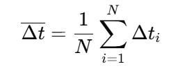
7.4 Interruption time metrics
Define interruption time per event as Δti.
Report:
- mean interruption time: Δt
- worst-case (P95 or max): Δt95 or Δtmax
For N mobility events:
For AR/VR and control use cases, P95 is often more important than mean.
7.5 Throughput stability
Instead of only peak throughput, measure variability.
If throughput samples are x1,x2,…,xn:
- average: μ
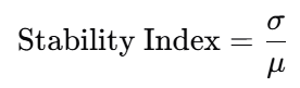
- standard deviation: σ
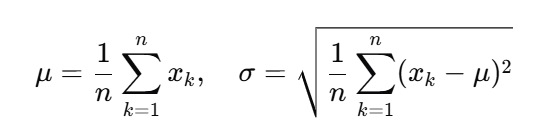
Then report a “stability index” such as σ/μ (lower is steadier):
7.6 Application-level KPIs (what stakeholders actually feel)
Mobility success should also be measured at the application level:
- VoIP MOS proxies, RTP packet loss bursts
- Video stall rate and time-to-first-frame recovery
- TCP goodput during HO windows
- UDP jitter and loss during HO windows
A key lesson: a “successful handover” in RAN counters can still produce unacceptable application interruptions if jitter spikes or path changes occur.
8) Common Tools Used in 5G Mobility Testing
The image lists tools commonly used:
- QXDM / QCAT
- TEMS / Nemo
- Wireshark NR
- Drive Test Equipment
Here’s how they fit together.
8.1 QXDM / QCAT (device-side protocol and modem logs)
Use these to capture:
- Layer 1/2/3 events (as exposed by chipset logging)
- measurement report triggers
- RRC messages and states
- timing around HO, RLF, beam failures
- modem behavior differences across firmware versions
These tools are essential when you need “why did the UE do that?”
8.2 TEMS / Nemo (drive testing suites)
Use these for:
- route-based testing (drive/walk)
- coverage mapping
- KPI dashboards during tests
- multi-device comparative testing
- geo-tagging of events
They help you correlate mobility failures with location, speed, and RF conditions.
8.3 Wireshark NR (packet analysis)
Use packet captures to understand:
- core-network signaling impacts
- application-level disruptions
- retransmissions and timeouts
- session continuity issues
Wireshark (plus appropriate capture points) is critical when handover is “radio OK” but the app still stalls.
8.4 Drive test equipment and setup
Mobility tests often require:
- calibrated antennas and RF chains for consistent measurements
- vehicle roof antennas for repeatable RF exposure
- GPS for precise speed/location
- synchronized time references across tools
For private 5G indoor mobility tests:
- trolleys, backpacks, or carts can serve as repeatable “walk test rigs”.
9) Test Methodology: Lab vs Field, Drive vs Walk vs High‑Speed
A robust mobility strategy uses multiple environments.
9.1 Lab testing (controlled)
Pros:
- repeatable RF conditions
- faster iteration and debugging
- controlled parameter sweeps
Cons:
- cannot fully reproduce real multipath, blockers, or urban clutter
- can miss interference patterns and neighbor-list realities
Lab is best for:
- regression testing after parameter or firmware changes
- beam management tuning
- baseline KPI generation
9.2 Field testing (real)
Pros:
- real propagation and interference
- realistic neighbor behavior
- real device thermal and power conditions
- captures “unknown unknowns”
Cons:
- less repeatable
- harder to isolate variables
- weather and network load variability
Field is essential for:
- final validation
- customer acceptance
- performance in real routes and buildings
9.3 Drive vs walk vs high-speed corridors
- Walk tests: indoor enterprise, campus, dense urban pedestrian
- Drive tests: suburban/urban roads, macro mobility
- High-speed tests: highways, rail corridors, special tracks
Don’t assume drive tests cover indoor enterprise mobility; they don’t. Similarly, indoor walk tests won’t reveal Doppler and high-speed HO effects.
10) Test Scenarios That Catch Real‑World Problems
Here are scenarios you should include in a serious 5G mobility test plan—especially for IoT and enterprise.
10.1 “Video continuity” scenario
The image gives a simple example: ensure a video call or streaming playback doesn’t drop while moving.
Turn that into a structured test:
- Start a stable stream (video call + parallel data transfer)
- Move through known HO zones (cell edges, beam edges)
- Measure:
- stall count,
- interruption time,
- throughput dips,
- MOS proxies (if applicable),
- HO counters and RLF
This scenario is a great baseline because it reveals both RAN and session continuity problems.
10.2 “Edge app continuity” scenario (IoT-relevant)
If you use edge compute or on-prem breakout:
- run an edge-hosted application session
- roam across cells/sectors
- verify whether:
- IP anchor changes,
- DNS resolution changes,
- packets are re-routed to a different edge
- latency spikes exceed app tolerance
This catches problems that pure radio KPIs miss.
10.3 “Beam-blockage” scenario (mmWave and dense mid-band)
- move behind obstacles (people, shelves, walls)
- measure beam recovery behavior:
- beam failure detection time
- recovery success rate
- throughput recovery time
This is crucial in warehouses, stadiums, and indoor venues.
10.4 “Inter-frequency fallback” scenario
- start on high-capacity layer (mid-band or mmWave)
- move into coverage-limited area
- validate the fallback to low-band (or another layer) without:
- long stalls
- excessive packet loss
- repeated reselections
10.5 “Ping‑pong stress” scenario
- choose a zone with overlapping coverage
- move back and forth near the boundary
- measure ping‑pong rate and adjust:
- hysteresis
- time-to-trigger
- offset parameters
- neighbor priority
10.6 “Load + mobility” scenario
Mobility problems often appear only under load.
- run mobility tests during peak hours
- add parallel traffic (uplink + downlink)
- measure HO success degradation under congestion
For private 5G, simulate load with traffic generators.
11) Troubleshooting Mobility: A Practical Root‑Cause Playbook
When mobility fails, teams often argue: “RAN issue” vs “UE issue” vs “core issue.” Use this structured approach.
11.1 Start with symptom classification
- Does the session drop (RRC connection lost)?
- Does RRC stay connected but throughput collapses?
- Do you see RLF?
- Do you see ping‑pong?
- Does it fail only on one device model or firmware?
11.2 Correlate timelines
Align timestamps across:
- UE logs (QXDM/QCAT),
- RAN counters/events,
- packet captures (Wireshark),
- GPS/location data.
Mobility debugging is mostly timeline forensics.
11.3 Diagnose measurement reporting
Common issues:
- wrong report triggers
- missing neighbor measurements
- poor filtering (too noisy) leading to unstable decisions
- measurement gaps not configured appropriately for inter-frequency
If reports are late, HO decisions will be late.
11.4 Diagnose HO preparation vs execution failures
- Preparation failure suggests target coordination issues or policy/load rejections
- Execution failure suggests target access was not feasible (coverage too weak, timing too tight)
11.5 Check for “HO succeeded but app died”
This is a classic case where:
- IP path changes,
- NAT rebinding breaks,
- UDP stream loses too many packets,
- TCP stalls due to reordering or temporary black holes.
The fix may be:
- transport tuning,
- session keepalive strategy,
- edge anchoring design,
- or core routing changes.
11.6 Look for beam-related issues
If throughput dips are periodic during motion:
- it may be beam switching instability
- beam recovery not fast enough
- blockage not handled properly
Beam problems can masquerade as handover problems.
11.7 Validate device firmware and modem settings
Some mobility issues are UE-implementation specific:
- aggressive power saving affecting measurements
- buggy beam management on certain bands
- handover timer differences across firmware
Mobility validation should always include a small “UE matrix”:
- different device models
- different firmware baselines
- different antenna setups (especially for vehicles/routers)
12) Mobility Testing for Private 5G and Industrial IoT
Private 5G introduces unique mobility patterns:
- indoor propagation
- metal reflections
- dynamic blockers (forklifts, people)
- often tighter control-loop requirements
12.1 What changes in private networks
- Smaller cells and higher density can increase HO frequency
- Indoor geometry creates sharp RF transitions
- Enterprises may require deterministic behavior for automation
12.2 Private 5G mobility test checklist
- Walk tests along critical operational routes (aisles, corridors, loading bays)
- Beam-blockage tests around machinery and shelving
- Coverage edge tests at doorways and between buildings
- Voice/data/industrial protocol tests simultaneously
- Failover tests: what happens if a small cell goes down?
- Interference tests (industrial EMI sources)
12.3 The “operational SLA” perspective
For industrial IoT, your KPI targets may be framed as:
- maximum interruption time ≤ X ms
- maximum packet loss burst ≤ Y packets
- HO success rate ≥ Z% over W hours
- zero RLF in safety zones
The network must be tested as an operational system, not just an RF system.
13) Mobility Testing for Connected Vehicles, Rail, and Drones
High-speed mobility introduces unique constraints:
- faster channel variation
- Doppler
- more frequent cell crossings
- higher probability of handover timing issues
- uplink reliability constraints for telemetry and video
13.1 Vehicle mobility tests: what to include
- highway routes with stable speed segments
- urban stop-and-go routes with multipath and blockage
- tunnels and underpasses
- on-ramp/off-ramp transitions
- cross-band scenarios (mid-band ↔ low-band)
Measure:
- HO success
- interruption time distribution (P50/P95)
- throughput stability
- uplink behavior (often the hidden issue)
- application-level continuity for telemetry/video
13.2 Rail mobility tests: corridor-based planning
Rail introduces:
- sustained high speeds
- consistent routes (good for repeatability)
- predictable cell crossing points
Good practice:
- run repeated passes to isolate parameter changes
- monitor where ping‑pong occurs near trackside cell overlaps
- validate performance in stations (dense load + mobility)
13.3 Drone mobility tests
Drones change altitude and geometry. Testing should include:
- vertical mobility (altitude changes)
- line-of-sight transitions
- handovers across sectors designed for ground users
- uplink video and command/control integrity
14) Reporting: How to Deliver Results Stakeholders Trust
Mobility testing often fails not because the network is bad, but because results are unclear. Your reporting should combine:
14.1 A one-page executive summary
- route/site overview
- headline KPIs (HO success, RLF, interruption time P95)
- top issues and business impact
- recommended remediation plan
14.2 Technical appendix for engineers
- full KPI definitions
- logs and traces
- event timelines
- maps of failure hotspots
- parameter snapshots
14.3 Reproducibility notes
Document:
- device models and firmware
- test tool versions
- antenna setups
- routes and timestamps
- weather and load conditions (if relevant)
Mobility results are otherwise hard to reproduce—and hard to act on.
15) FAQs
What is mobility testing in 5G?
5G mobility testing validates that a UE maintains connectivity and application continuity while moving across beams, cells, frequencies, or radio technologies. It covers handover success, beam switching, measurement reporting, session continuity, and performance under speed.
What are the key components of 5G mobility testing?
Core components include handover (HO), measurement reporting, beam mobility, high‑speed mobility, and session continuity.
What KPIs matter most for 5G mobility?
The most actionable KPIs are handover success rate, radio link failure (RLF) rate, interruption time (mean and P95), ping‑pong rate, beam switching delay, and throughput stability during mobility.
What tools are commonly used for 5G mobility testing?
Common tools include QXDM/QCAT for UE protocol logs, TEMS/Nemo for drive/walk testing workflows, Wireshark NR for packet analysis, and specialized drive test equipment for GPS-synchronized RF measurements.
Why do “successful” handovers still cause app problems?
Because application continuity depends on more than RAN signaling. IP path changes, jitter spikes, packet loss bursts, NAT rebinding, edge breakout changes, or transport timeouts can break sessions even when the handover completes.
Final Takeaway: Mobility Testing Is the Real Proof of 5G
Static speed tests don’t prove a network is production-ready. Mobility testing does.
A strong 5G mobility validation program—covering handover, measurement reporting, beam mobility, high-speed movement, and session continuity—turns “5G coverage” into 5G reliability.
For IoTWorlds readers building enterprise networks, connected fleets, or edge-first applications, mobility testing is how you ensure that your system doesn’t just connect—it keeps working when the real world moves.